MODULE 1: JOINT MODEL PERSONALIZATION
In this module, you will used the OpenSim Scale Model tool and the NMSM Pipeline Joint Model Personalization (JMP) tool to personalize lower body joint functional axis positions and orientations in a scaled generic full-body OpenSim model. The personalization process will be performed using marker motion data obtained from the isolated joint motion trials as well as the gait trial.
Task 1: Model Scaling
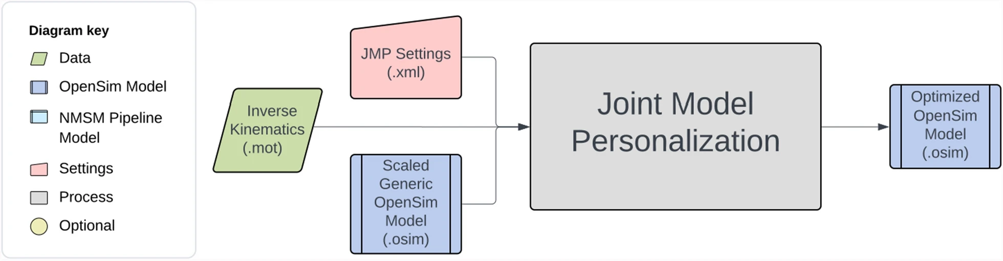
The starting point for Joint Model Personalization is always a scaled generic OpenSim model (or, when available, an OpenSim model possessing subject-specific bone models obtained from the subject’s imaging data). For the present project, you will scale a generic full-body OpenSim model (Ragagopal et al., 2016) modified to improve kinematic modeling of the ankles and knees (van den Bogert et al., 1994; Hammond et al., 2025) and musculoskeletal geometry modeling of the knees and hips (Lai et al., 2017; Ulrich et al., 2022). However, to improve the subsequent Ground Contact Model Personalization process, you will follow a non-standard model scaling process as described below. The interaction between tool settings, data, and models required to perform this module task is shown in the figure below:
To perform the non-standard model scaling process, you will work with two generic OpenSim models:
Full_Body_Walking_Model.osim– This model is the generic full-body OpenSim model described above.To facilitate the model scaling process, some joints are already locked in the model that are typically unlocked and unlocked other joints in the model that are typically locked, as summarized in the tables below.
Notable locked joints in the model include the following:
Joint To Be Unlocked Later To Remain Locked pelvis_list ✓* knee_adduction_r ✓ Knee_adduction_l ✓ mtp_angle_r ✓ mtp_angle_l ✓ lumbar_bending ✓* lumbar_rotation ✓* pro_sup_r ✓ pro_sup_l ✓ Whether or not the starred (*) joints should be locked depends on the subject being modeled. Locking these joints during the model scaling process helps ensure that the final model pose in the standing static trial is physically realistic for this particular subject (e.g., the pelvis is level when viewed from the front, the torso is not tilted to the side or twisted about a vertical axis).
Notable unlocked joints in the model include the following:
Joint To Be Unlocked Later To Remain Locked knee_frontal_r ✓ knee_frontal_l ✓ The knee frontal angles and the knee adduction angles are similar to each other but serve two different purposes. The knee frontal angles are used in the definition of the knee joints. By unlocking these angles during the model scaling process, we ensure that the static frontal plane alignment of both knees in the model is realistic for the subject (i.e., both knees should end up with a slight varus, or bow-legged, alignment) when the model is in the static pose. Having the correct frontal plane knee alignment in the static pose is important since this pose is used to “glue” the experimental markers onto the model’s body segments. If the frontal plane knee alignment is incorrect in the static pose, then the tibial markers will not be placed on the model correctly at the end of the model scaling process. In contrast, the knee adduction angles are used for calculating the knee adduction moments via inverse dynamics. By keeping these angles locked, we create a joint axis that is directed along the X axis of each tibia and that OpenSim can use for calculating a knee adduction moment.
Feet_Only_Walking_Model.osim– This model contains only the feet from the full-body OpenSim model. This model is needed so that the feet in the model can be properly aligned with the experimental foot marker locations in the static standing trial. If a foot is misaligned with respect to its experimental foot marker locations, then the personalized ground contact model to be developed later for that foot will not work properly.To construct this model, the following entities are removed from the full-body model:
- All bodies except the right and left calcaneus and toes bodies.
- All joints except the right and left mtp joints.
- All constraints and forces.
- All markers except for markers attached to the calcaneus and toes bodies of each foot.
In addition, following entities are added to the feet-only model:
- Two 6 DOF Custom Joints to connect the calcaneus body of each foot to the ground. The rotation sequence for the right calcaneus with respect to ground is defined as (-X, -Y, Z), while the rotation sequence for the left calcaneus with respect to ground is defined as (X, Y, Z). In this way, the same rotations applied to both feet produce anatomically consistent poses for the two feet (e.g., both feet toed out by the same amount). Both X rotations and both Z rotations are locked to zero to prevent each foot from tilting to one side or the other and frontward or backward.
- A Coordinate Coupler Constraint to make the Y translation of the left calcaneus the same as that of the right calcaneus. This constraints ensures that both feet are the same height above the ground in the standing static pose.
The only experimental data needed for the model scaling process is marker data contained in the static trial datafile
Trial04_Static_markers_reordered.trc. In addition, you will need to know the mass of the subject, which was 72.8 kg based on force plate data collected during the static standing trial.When iterating the model scaling steps outlined below, you should always select the Preview static pose (no marker movement) checkbox at the bottom of the Scale Tool menu. This selection will cause the model scaling process to be performed but without replacing markers on the scaled model with the experimental marker locations. You should then select File ⇨ Preview Experimental Data in the OpenSim GUI to visualize the experimental marker data from the static trial. You can then compare how far the markers on the scaled model are away from the corresponding experimental marker locations.
Step 1: Perform model scaling for the full-body model
Load the full-body model Full_Body_Walking_Model.osim into the OpenSim GUI.
Select the Scale Model tool to scale the full-body model using the static trial datafile Trial04_Static_markers_reordered.trc.
On the main Scale Tool menu, make the output model name Full_Body_Walking_Model-Scaled, select Scale Model and Adjust Model Markers, and pick a small time window of roughly 0.1 sec for averaging the static trial marker data. Set the scaled model mass to 72.8 kg, and check Preserve mass distribution during scale.
On the Scale Factors tab, create measurements called PelvisWidth (for scaling the pelvis body) using the R_ASIS and L_ASIS markers, FemurLengthR (for scaling the right femur and patella bodies) using the R_ASIS and R_Knee_Lateral markers, TibiaLengthR (for scaling the right tibia body) using the R_Knee_Lateral and R_Ankle_Lateral markers, FemurLengthL (for scaling the left femur and patella bodies) using the L_ASIS and L_Knee_Lateral markers, TibiaLengthL (for scaling the left tibia body) using the L_Knee_Lateral and L_Ankle_Lateral markers, FootLength (for scaling the talus, calcaneus, and toes bodies on both legs) using heel and toe markers on both feet, and ForearmLength (for scaling the radius, ulna, and hands on both arms) using the elbow and wrist markers on both arms. You will use different femur and tibia lengths for the two legs since the subject had a slight leg length discrepancy. Do not scale the pretalus body in either leg, since it is a massless intermediate reference frame that only adds a rotational offset as needed to implement the van den Bogert et al. (1994) ankle model. Since the shoulder markers where not placed on the shoulder but rather on the straps of a safety harness behind the shoulders, do not use the shoulder markers to create a measurement for estimating torso height or upper arm length. Instead, input manual scale factors for torso body and the humerus bodies, and try different values until your scaled model matches the elbow and wrist marker positions well. You will probably need to make the scale factor for the torso body less than 1 and the scale factor for the two humerus bodies greater than 1.
On the Static Pose Weights tab under Marker Name, select markers and associated weights as follows:
a. The heel and toe markers on both feet using a weight of 10 to cause experimental foot marker positions to be matched closely. Do not pick any other foot markers. Note that the feet will not invert or evert during the scaling process since the subtalar joint axis on both feet has been temporarily locked to a value of 0.
b. All medial and lateral ankle and knee markers using a weight of 1.
c. The two ASIS markers and the central sacral marker using a weight of 10 to cause experimental pelvis marker positions to be matched closely.
d. The chest marker and the two elbow and wrist markers using a weight of 1.
By matching the foot and pelvis markers closely, we will ensure that the lower body joint angles represent the subject’s experimental leg position well. Since the shoulder marker positions are not closely related to the anatomical shoulder locations, do not select the shoulder markers on this tab.
- Run the Scale Model tool to create a scaled full-body model. Note that this scaled model will have adjusted mass properties.
- Click on the Navigator tab and save the scaled model by right-clicking on it and selecting Save As. Use
Full_Body_Walking_Model-Scaled.osimas the saved model name.
Step 2: Perform model scaling for the feet-only model
- Load the feet-only model
Feet_Only_Walking_Model.osiminto the OpenSim GUI. - Select the Scale Model tool to scale both feet using the static trial datafile
Trial04_Static_markers_reordered.trc. - On the main Scale Tool menu, make the output model name
Feet_Only_Walking_Model-Scaled, select Scale Model and Adjust Model Markers, and pick the same small time window of 0.1 sec for averaging the static trial marker data. Don’t worry about the scaled model mass at this point. - On the Scale Factors tab, create a Foot`Length scale factor using the heel and toe markers for both feet, just like for the full-body model.
- On the Static Pose Weights tab, select only the heel and toe markers on each foot, use a weight of 1 for the heel markers, and use a weight of 10 for the toe markers. Give the toe markers more weight since we trust their height above the floor more than we trust the height of the heel markers above the floor.
- Run the Scale Model tool to create the scaled model with the experimental markers properly attached to each foot.
- Save the scaled model by right-clicking on it and selecting Save As. Use
Feet_Only_Walking_Model-Scaled.osimas the saved model name.
Step 3: Adjust the scaled full-body model for subsequent tasks
Several remaining adjustments must be made to the scaled full-body OpenSim model Full_Body_Walking_Model-Scaled.osim before Model Personalization and Treatment Optimization tasks can be performed:
Copy the scaled OpenSim model
Full_Body_Walking_Model-Scaled.osimto a new file calledFull_Body_Walking_Model-Scaled_Adjusted.osim.Open model
Full_Body_Walking_Model-Scaled_Adjusted.osimin a text editor and make the following three changes:a. Change the model name at the top of the file to
Full_Body_Walking_Model-Scaled_Adjusted.b. Correct an OpenSim bug where the
<scale>field in some<TransformAxis>blocks contains a negative number. Search for<scale>in your model and replace with<scale>(i.e., minus sign deleted) to eliminate non-physical negative scale factors. This OpenSim bug should be fixed in version 4.6 whenever it is released.c. Copy the foot marker locations from OpenSim model
Feet_Only_Walking_Model-Scaled.osimand replace the corresponding foot marker locations in OpenSim modelFull_Body_Walking_Model-Scaled_Adjusted.osim, which ensures that the foot marker locations in the full-body model are as consistent as possible with foot marker locations when both feet were flat on the ground.Load model
Full_Body_Walking_Model-Scaled_Adjusted.osiminto the OpenSim GUI.On the Coordinates tab, unlock the following locked coordinates in the model:
pelvis_list
mtp_angle_r
mtp_angle_l
lumbar_bending
lumbar_rotation
On the Coordinates tab, set the value of the following unlocked coordinates to 0 and then lock them:
knee_frontal_r
knee_frontal_l
Re-save the modified model as
Full_Body_Walking_Model-Scaled_Adjusted.osim.
Task 2: Joint Model Personalization
Now that you have an appropriately scaled full-body walking model with correctly place markers on the body segments (especially the feet), you are ready to personalize the lower body kinematic structure of your model using the NMSM Pipeline’s Joint Model Personalization tool. The interaction between tool settings, data, and models required to perform this module task is shown in the figure below:
The experimental data needed for the Joint Model Personalization process is marker data contained in the isolated joint motion, gait, and combined datafiles located in the JMP directory and listed below:
Trial06_AnkleR_markers_cropped.trc– 101 time points of marker data for one cycle of isolated right ankle joint motionTrial07_KneeR_markers_cropped.trc– 101 time points of marker data for one cycle of isolated right knee motionTrial08_HipR_markers_cropped.trc– 101 time points of marker data for one cycle of isolated right hip motionTrial09_AnkleL_markers_cropped.trc– 101 time points of marker data for one cycle of isolated left ankle motionTrial10_KneeL_markers_cropped.trc– 101 time points of marker data for one cycle of isolated left knee motionTrial11_HipL_markers_cropped.trc– 101 time points of marker data for one cycle of isolated left hip motionTrial12_Gait_LowerBody_markers_cropped.trc– 101 time points of marker data for one cycle of reference walking motionTrial04_Static_markers_cropped.trc– 5 time frames of marker data from the static standing trialTrials06_07_08_LegR_markers_cropped.trc– 303 time points of concatenated marker data from all isolated joint motion trials for the right leg onlyTrials09_10_11_LegL_markers_cropped.trc– 303 time points of concatenated marker data from all isolated joint motion trials for the left leg onlyTrials06_07_08_09_10_11_BothLegs_markers_cropped.trc– 606 time points of concatenated marker data from all isolated joint motion trials for both legsTrials08_11_BothHips_markers_cropped.trc– 202 time points of concatenated marker data from the isolated hip motion trials for both legsTrials_Joints_Gait_markers_cropped.trc– 707 time points of concatenated marker data from all isolated joint motion trials plus the gait trial
Each datafile contains only lower body markers from the pelvis down, as these markers are the only ones needed to personalize lower body joint functional axes and joint centers. The marker datafile for each type of motion has been splined and cropped to 101 time points representing one complete motion cycle. In this way, each type of motion contributes the same number of marker distance errors to the JMP optimization process when datafiles from multiple types of motions are concatenated into a single combined datafile.
For this module task, you will perform the Joint Model Personalization process three times for all lower body joints in the scaled adjusted model by following a three-step process:
Step 1: You will personalize the lower body joints individually. In this step, you will perform the personalization process for one (ankle and knee) or two (hips) joints at a time using marker data from the isolated joint motion trials, always running a new JMP task manually starting from the original scaled adjusted OpenSim model. This module step is where you will explore how to formulate an appropriate JMP problem for each type of lower body joint. You will use the knowledge gained in this step to formulate the JMP problems that you will solve in the subsequent two steps.
Step 2: You will personalize the lower body joints sequentially. In this step, you will perform the personalization process one joint at time using marker data from the isolated joint motion trials, automatically running a sequence of JMP tasks that always starts from the updated OpenSim model produced by the previous JMP task. The last JMP task in the sequence will utilize the gait trial marker data to personalize all joints together.
Step 3: You will personalize the lower body joints simultaneously. In this step, you will perform the personalization process for all joints together using a concatenated datafile containing marker data from all isolated joint motion trials plus the gait trial. Only a single JMP task will be used for this step.
With the sequential approach, improving marker tracking accuracy for one joint (e.g., the knee) could potentially worsen marker tracking accuracy for another joint (e.g., the ankle), but the benefit is reduced computation time compared to the simultaneous approach. Thus, for this module task, you will be investigating the accuracy-speed tradeoff between the sequential and the simultaneous approaches.
For all three steps, you will create a JMP settings file using the Joint Model Personalization tool in the OpenSim GUI. For each JMP settings file, you should use the following general guidelines when creating a JMP task:
Select the marker motion datafile that corresponds to the single joint (ankle or knee), two joint (hips), or multiple joint (gait, or all joints + gait) optimization problem you are trying to solve.
Accept the default time range so that you will also get one complete motion cycle of marker data possessing 101 time points for each type of motion included in the datafile.
Select markers from the following list of “dynamic” markers so that markers are present on the parent and child bodies of all joints included in a JMP task (e.g., when personalizing the right knee functional axis, select all markers on the right femur and right tibia):
• R_ASIS, L_ASIS, and Sacral
• R_Thigh_Superior, R_Thigh_Inferior, R_Thigh_Lateral, and R_Thigh_Posterior
• R_Shank_Superior, R_Shank_Inferior, R_Shank_Lateral, and R_Shank_Posterior
• R_Heel, R_Midfoot_Superior, and R_Midfoot_Lateral
• L_Thigh_Superior, L_Thigh_Inferior, L_Thigh_Lateral, and L_Thigh_Posterior
• L_Shank_Superior, L_Shank_Inferior, L_Shank_Lateral, and L_Shank_Posterior
• L_Heel, L_Midfoot_Superior, and L_Midfoot_Lateral
Select joints for which parent and/or child frame rotations are to be adjusted, and select bodies for which uniform scaling is to be applied and/or markers are to be moved along selected body axes.
For each selected joint, do not select any parent or child frame translations. This decision will prevent joints from disarticulating (e.g., the head of the femur will not pull out of the socket in the pelvis).
For each selected joint, do not select any parent or child frame rotation about the primary axis of rotation for the joint (e.g., the Z axis for the knee). This decision will prevent the optimization from trying to change a joint orientation that is redundant with motion about the primary joint functional axis.
For each selected joint, keep the default rotation bounds at 0.5, noting that this value is actually in radians and not degrees.
To personalize an ankle joint, select the ankle joint and corresponding subtalar joint on the desired side, and do not select any bodies. To personalize a knee joint, select the knee joint on the desired side, and do not select any bodies. To personalize both hip joints together, select the pelvis body and allow it to be scaled, and do not select any joints. When personalizing all joints together, consider selecting the tibia and/or femur bodies and allowing both bodies to be scaled and/or markers to be moved along the body segment X and Y directions.
Never allow markers to be moved on the pelvis, calcaneus, or toes bodies. We trust the marker locations on these bodies (especially on the feet), so allowing them to move is likely to result in an anatomically unrealistic solution.
To decide which parent and child frame rotations should be changed for which joints, use the information provided in the table below:
| Joint | Functional Axis | Parent Frame Rotation | Child Frame Rotation | ||||
|---|---|---|---|---|---|---|---|
| X | Y | Z | X | Y | Z | ||
| Subtalar | X | ✓ | ✓ | ✓ | |||
| Ankle | Z | ✓ | ✓ | ||||
| Knee | Z | ✓ | ✓ | ✓ | ✓ | ||
| Hip | N/A | ||||||
These parent and child frame rotation changes ensure that the final joint structure remains consistent with the joint’s physical anatomy. Feel free to modify these choices if you think that some alternate settings might work better!
Personalize the orientation of a joint functional axis only if at least ~30 deg of rotation occurs about that axis in the marker data being used for the JMP run (e.g., in the gait trial marker data, the subtalar joint experiences a rotation of < 30 deg, so it’s functional axis should not be personalized using gait trial data alone) (Chèze et al., 1998).
For each JMP settings file that you create through the OpenSim GUI, open the settings file in a text editor, increase the value of
<function_tolerance>to 1.0e-04, and increase the value of<max_function_evaluations>to 1000. These changes will make your JMP runs converge faster while also allowing enough iterations for tasks that require a large number of function evaluations per iteration.
If you want to read a previously-created JMP settings file back into the OpenSim GUI to modify it, you will need to re-save your settings file with a new name. If you re-save with the same file name, your changes will not be saved in our original settings file.
Once you have created and saved a JMP settings file, you will run the file and generate results by following the instructions below:
- Open Matlab, load the NMSM Pipeline project if necessary, and change directories to where your JMP settings file is located.
- Run the JMP tool in Matlab using the settings file you just saved by inputting the following commands into Matlab:
parpool
JointModelPersonalizationTool("JMP_Settings.xml")
In this example, the name of the JMP settings file is JMP_Settings.xml. The parpool command will start a parallel pool of workers (which can take a minute or so) if your computer has multiple cores.
After completing a JMP run, always visualuze your post-JMP model in the OpenSim GUI.
When visualizing a post-JMP model, you should not only look at how the model looks in the default pose but also run an OpenSim Inverse Kinematics analysis on the post-JMP model using the marker motion .trc file used for your JMP optimization. If your settings file allows unrealistic changes in joint positions or orientations, body scaling, or marker locations on the body segments, you may get significantly reduced marker distance errors but an anatomically unrealistic model.
- Plot your pre- and post-JMP marker distance errors using the Matlab function
plotJmpResultsFromSettingsFile.mas shown below:
plotJmpResultsFromSettingsFile("JMP_Settings.xml")
This function will also output the average and maximum marker distance errors for your pre- and post-JMP OpenSim models.
Before performing the three Joint Model Personalization steps below, you should review the section describing the Joint Model Personalization process in our recently published journal article describing the design and functionality of the NMSM Pipeline (Hammond et al., 2025). That section provides helpful information on how to formulate Joint Model Personalization problems that reduce marker tracking errors while respecting the anatomic structure of the joints (e.g., ensuring that the “ball” at the head of the femur does not dislocate from the “cup” in the pelvis).
Step 1: Perform joint model personalization for lower body joints individually
Load the scaled adjusted model
Full_Body_Walking_Model-Scaled_Adjusted.osiminto the OpenSim GUI. NMSM Pipelilne tools will not be accessible in the OpenSim GUI Tools menu unless a model to personalize is loaded first.Select Tools ⇨ User Plugins ⇨ rcnlPlugin.dll to load the NMSM Pipeline tools into the OpenSim GUI Tools menu.
Select the Joint Model Personalization tool to set up one JMP task to be saved as one JMP settings file to personalize one joint (or two joints for the hips) at a time. Repeat this process for the remaining joints, always using the same scaled adjusted OpenSim model as the initial model, and always using isolated joint motion data as the input marker motion data. First, personalize the right ankle by creating a JMP settings file just for the right ankle using the isolated joint motion datafile for the right ankle. Next, personalize the right knee by creating a JMP settings file just for the right knee using the isolated joint motion datafile for the right knee. Finally, personalize both hips together by creating a JMP settings file for both hips using the isolated joint motion datafile for both hips. You do not need to personalize the ankle and knee joints on the left side, since performing the process for just the right side will provide the knowledge you need to perform the next two steps.
Once a JMP settings file is completed, save it to your hard disk using the Save command at the bottom of the tool menu. Name these three JMP settings files
JMP_Settings_RAnkle.xml,JMP_SettingsRKnee.xml, andJMP_Settings_BothHips.xml.
Step 2: Perform joint model personalization for lower body joints sequentially
Load the scaled adjusted model
Full_Body_Walking_Model-Scaled_Adjusted.osiminto the OpenSim GUI. NMSM Pipelilne tools will not be accessible in the OpenSim GUI Tools menu unless a model to personalize is loaded first.Select Tools ⇨ User Plugins ⇨ rcnlPlugin.dll to load the NMSM Pipeline tools into the OpenSim GUI Tools menu (if you have not done so already).
Select the Joint Model Personalization tool to set up a sequence of 6 JMP tasks to be saved as one JMP settings file that personalizes lower body joints one at a time. Each JMP task in the sequence should use the appropriate marker motion data for that task (e.g., the JMP task that personalizes the right ankle should use marker motion data from the isolated right ankle motion trial). As each task in the sequence is completed, the next task will use as its starting point an updated OpenSim model produced by the previous task. It is up to you to define the JMP task sequence. The only limitation is that the gait trial must be used alone as the final task in the sequence. Possible task sequences from which to choose are listed below:
AnkleR    ⇨  AnkleL  ⇨  KneeR     ⇨  KneeL   ⇨  BothHips  ⇨  Gait
AnkleR    ⇨  AnkleL  ⇨  BothHips  ⇨  KneeR   ⇨  KneeL     ⇨  Gait
KneeR     ⇨  KneeL   ⇨  BothHips  ⇨  AnkleR  ⇨  AnkleL    ⇨  Gait
KneeR     ⇨  KneeL   ⇨  AnkleR    ⇨  AnkleL  ⇨  BothHips  ⇨  Gait
BothHips  ⇨  AnkleR  ⇨  AnkleL    ⇨  KneeR   ⇨  KneeL     ⇨  Gait
BothHips  ⇨  KneeR   ⇨  KneeL     ⇨  AnkleR  ⇨  AnkleL    ⇨  Gait
Select the sequence that you believe has the best chance of producing the lowest marker distance errors. You need to perform the sequential approach for only one sequence!
- Name your output model file
Full_Body_Walking_Model-JMP_Sequential.osim - Once your JMP settings file is completed, save it to your hard disk using the Save command at the bottom of the tool menu and name it
JMP_Settings_Sequential.xml. - Run Joint Model Personalization using the instructions provided above.
Step 3: Perform joint model personalization for lower body joints simultaneously
- Load the scaled adjusted model
Full_Body_Walking_Model-Scaled_Adjusted.osiminto the OpenSim GUI. - Select Tools ⇨ User Plugins ⇨ rcnlPlugin.dll to load the NMSM Pipeline tools into the OpenSim GUI Tools menu (if you have not done so already).
- Select the Joint Model Personalization tool to set up a single JMP task to be saved as one JMP settings file that personalizes all lower body joints together. The one JMP task should use the marker motion data from each isolated joint motion trial plus the gait trial. In this way, all functional axes of the lower body joints will be exercised within a single datafile. The fact that the motions are discontinuous between one motion and the next is irrelevant, since internally JMP performs repeated OpenSim Inverse Kinematics analyses, and these analyses do not require continuity between time frames of marker data.
- Name your output model file
Full_Body_Walking_Model-JMP_Simultaneous.osim - Once your JMP settings file is completed, save it to your hard disk using the Save command at the bottom of the tool menu and name it
JMP_Settings_Simultaneous.xml. - Run Joint Model Personalization using the instructions provided above.
Step 4: Select the model with the best personalized joints
• Compare the average and maximum marker distance errors for the gait trial produced by the sequential and simultaneous approaches.
• Identify the approach that produced the lowest errors for the gait trial marker data and that is also the most realistic physically (as determined by visual inspection in the OpenSim GUI – e.g., look for approximate bilateral symmetry in joint coordinate system orientations in the body segments, approximate bilateral symmetry in joint angles in the static pose, reasonable body scale factors, reasonable marker location changes).
• Copy the OpenSim model produced by the “best” approach and give it the new name Full_Body_Walking_Model-Post_JMP.osim.
• In a text editor, open the model and change the model name at the top of the file to Full_Body_Walking_Model-Post_JMP.
Step 5: Redefine the default pose in preparation for Ground Contact Model Personalization
Load model
Full_Body_Walking_Model-Post_JMP.osiminto the OpenSim GUI.Select the Inverse Kinematics tool and run an inverse kinematics analysis using the static trial marker data with the following marker/coordinate selections and weights:
Deselect:
All medial and lateral knee and ankle markers
The non-central sacral markers
Both shoulder markers
The back marker
Select:
All foot and remaining pelvis markers using a weight of 10
All tibia, arm, and chest markers using a weight of 1
All thigh markers using a weight of 0.1
The lumbar_rotation coordinate, leave the Default Value as zero, and set the weight to 0.1.
These weights represent good choices when performing an inverse kinematics analysis for a motion trial. Lightly tracking a lumbar_rotation coordinate value of 0 will prevent the torso from twisting unrealistically since a single marker near the midline of the torso is not sufficient to make the lumbar_rotation unique.
Make the static pose the new default pose by selecting the Coordinates tab, then Poses>Set Default. Making this final static pose the new default pose will place the feet in the correct pose and at the correct height above the floor for contact element placement on the bottom of each foot during the Ground Contact Model Personalization process in the next module.
Save the model in this final pose by right-clicking on it and selecting Save.
Take a screen shot of the model in the final static pose with the experimental markers shown as well.
Deliverables
OpenSim Scale Model tool settings file for scaling
Feet_Only_Walking_Model.osimalong with scaled model fileFeet_Only_Walking_Model-Scaled.osim.OpenSim Scale Model tool settings file for scaling Full_Body_Walking_Model.osim along with scaled model file
Full_Body_Walking_Model-Scaled.osim.Scaled adjusted model file
Full_Body_Walking_Model-Scaled_Adjusted.osim.Screen shot of model
Full_Body_Walking_Model-Scaled_Adjusted.osimin the static pose found by inverse kinematics with the experimental markers shown as well (screenshot shown below):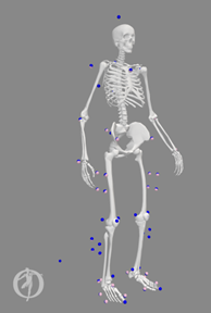
Wall clock time along with pre- and post-JMP marker distance errors for each JMP run performed in the three steps above (complete the table below):
A plot comparing pre- and post-JMP marker distance errors across all time frames for each of the 5 JMP runs shown in the table above.
A JMP settings file for each of the 5 JMP runs shown in the table above.
Post-JMP OpenSim model
Full_Body_Walking_Model-JMP_Sequential.osimproduced by the sequential approach andFull_Body_Walking_Model-JMP_Simultaneous.osimproduced by the simultaneous approach.A description of the task sequence that you chose to use for the sequential approach along with a brief argument for why you believe this sequence might produce lower marker distance errors than would other sequences.
A brief paragraph explaining when researchers should use the sequential approach and when they should use the simultaneous approach for Joint Model Personalization.